LED Strip Lighting System Design: Voltage Drop, Load Calculation, and Best Practices
How LED Strips Work
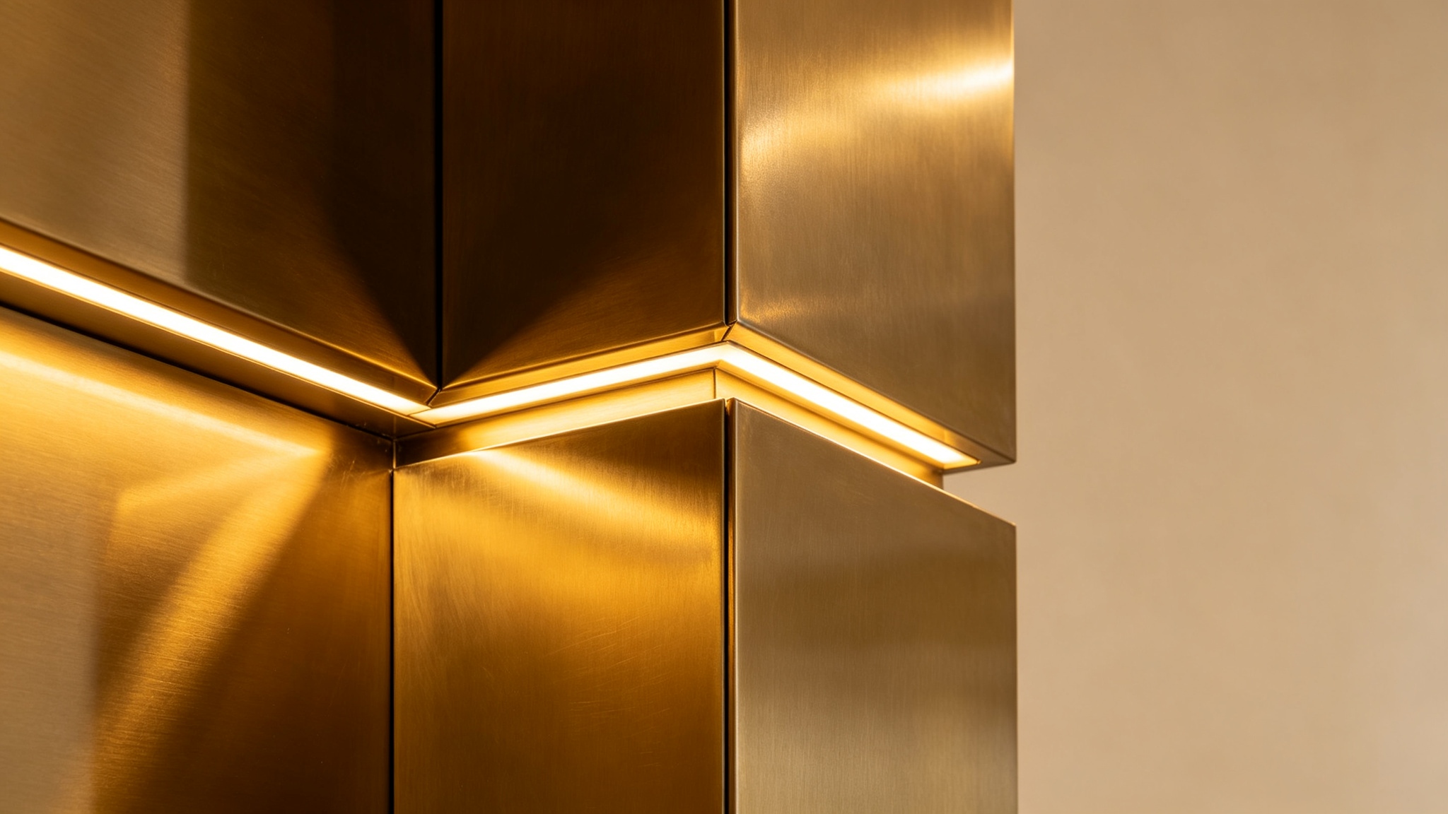
A typical LED strip consists of a flexible PCB with surface-mount LEDs at regular intervals—30, 60, 120, or 240 LEDs per meter. LEDs are arranged in parallel groups, each group containing a series string (typically 3 LEDs for 12V, 6 for 24V) and a current-limiting resistor. Strips operate at fixed voltage—12V or 24V DC most common—and on-board resistors ensure each group draws rated current at correct voltage.
Power consumption is specified in watts per meter (W/m), ranging from 4.8W/m (low-density) to 19.2W/m (high-density), with specialized strips reaching 24W/m+. Total power of a run = W/m × length. A 5m run of 14.4W/m consumes 72W. Because strips are constant-voltage devices, they require constant-voltage drivers with matching output voltage and sufficient power/current rating.
Load Calculation: More Than Wattage
The first design step is calculating total load from W/m and total length, but several factors complicate this.
Rated W/m is measured at nominal voltage and 25°C. As the strip heats, LED forward voltage decreases slightly (negative temperature coefficient ~-2mV/°C per LED), causing current to increase at constant voltage—usually 2% to 5%, meaning actual operating power may exceed rated.
Power consumption varies between batches and manufacturers. Two "14.4W/m" strips may actually draw 13.5W/m and 15.2W/m depending on LED binning and resistor tolerance. For critical installations, measure actual current rather than relying solely on datasheets.
Most importantly, size the driver with headroom. A common rule: load the driver to no more than 80% of rated output power. This provides margin for the variations above, inrush current at turn-on, and ambient temperature derating. Running a driver at 100% continuously accelerates electrolytic capacitor aging and reduces lifespan. A 100W driver at 72W load (72%) runs cooler and lasts far longer than the same driver at 100W. For a 72W load, a 100W driver is appropriate; a 75W driver (96% load) is under-sized for reliable long-term operation.
Voltage Drop: The Hidden Problem
Voltage drop is the most common cause of poor strip performance. Copper traces on the strip PCB have finite resistance; current flowing through them produces voltage drop along the run. Voltage at the far end is lower than at the feed end, and because LED brightness is voltage-sensitive, the far end appears dimmer and may shift color temperature.
Severity depends on three factors: operating voltage, current per meter, and run length. A 12V strip is far more susceptible than 24V because, for the same W/m, 12V draws twice the current (I = P/V). Since voltage drop is proportional to current (V_drop = I × R), a 12V strip experiences twice the absolute drop of an equivalent 24V strip. Moreover, at half the operating voltage, the same absolute drop represents twice the percentage change, making brightness difference twice as noticeable.
General guideline: 12V strips should not exceed 5m in a single continuous run, and 24V strips should not exceed 10m, without additional feed points. These limits assume standard 2-oz copper traces and moderate density (up to 14.4W/m). Higher-density strips (19.2W/m+) have shorter limits; some manufacturers specify max 3m for 12V high-density strips.
When a run exceeds max length, solutions include: adding a power feed at the midpoint or both ends (splitting into shorter segments); using heavier-gauge parallel power wires ("power bus") alongside the strip with regular connection points to inject voltage; or, for very long installations, preferring 24V over 12V and using multiple drivers for different zones.
Voltage drop also occurs in wiring between driver and strip. If the driver is far from the strip (e.g., 10m from a ceiling junction box to a cove), account for wire drop. Use heavier gauge (18 AWG or 16 AWG for low-voltage DC) and keep runs short. More than 5% drop in connecting wiring is generally unacceptable.
System Architecture: Single vs. Multiple Drivers
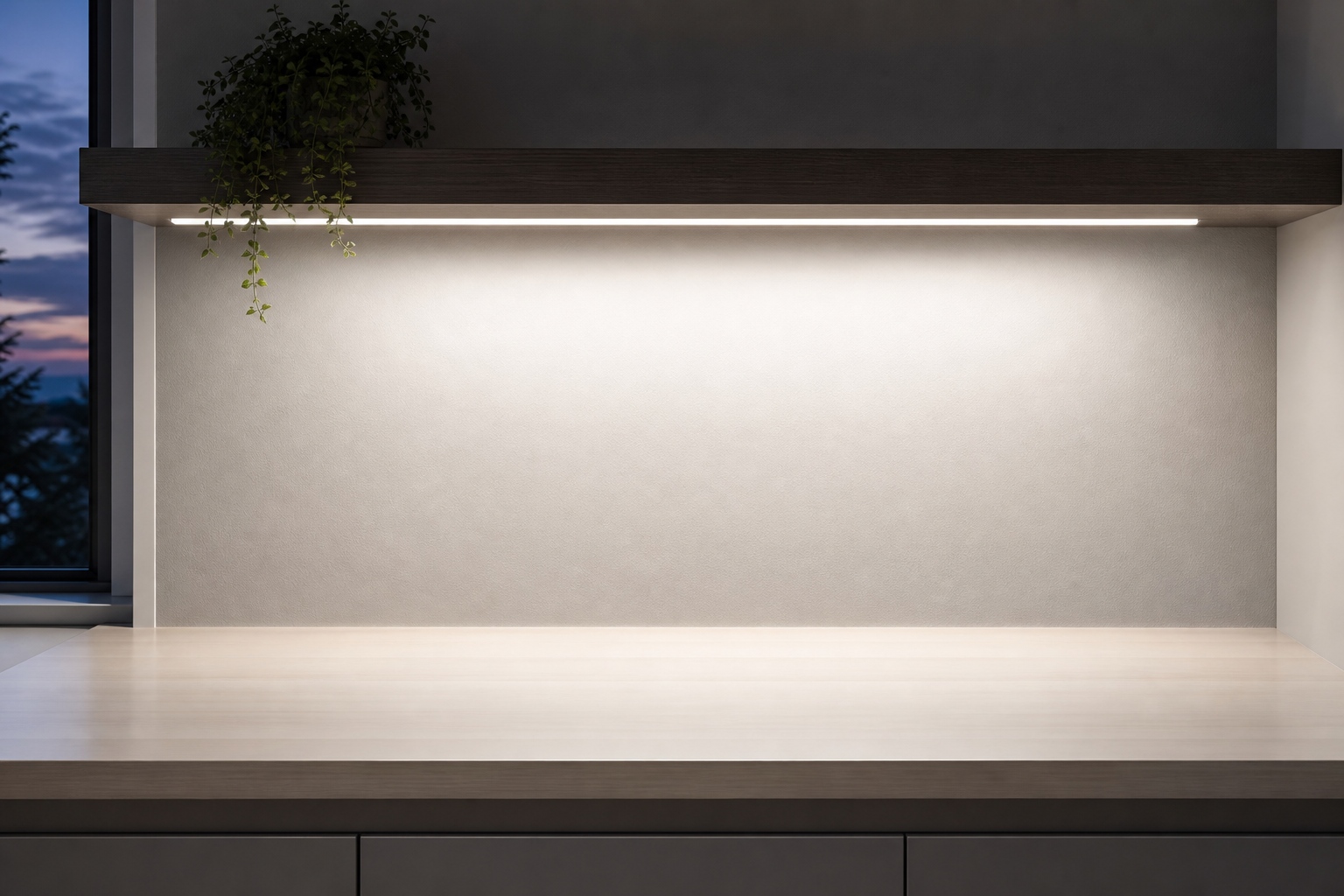
For small installations—a single under-cabinet run, a small cove—one driver suffices. For larger installations, choosing one large driver vs. multiple smaller ones requires thought.
A single large driver simplifies wiring and reduces cost, but creates a single point of failure: if it fails, the entire system goes dark. It also requires all runs wired to a central location, meaning long low-voltage runs with significant drop. And a large driver may be overkill for small zones, wasting energy and generating unnecessary heat.
Multiple smaller drivers offer redundancy and flexibility. Each zone can be controlled independently (useful for scenes and dimming). Drivers can be located closer to loads, reducing low-voltage wire drop. If one fails, only one zone is affected. Trade-offs: higher cost, more complex wiring (each driver needs its own AC connection), more absolute failure points.
For most commercial and high-end residential installations, a distributed architecture with multiple medium drivers (30W–100W each) is preferred, balancing cost, reliability, performance, and zone-based control.
Dimming and Installation Best Practices
When dimming strip systems with TRIAC-dimmable constant-voltage drivers, additional considerations apply. Dimming performance depends on total load—if load is too low, the dimmer may flicker or fail. Even a 2m run of 14.4W/m draws 28.8W (usually sufficient), but a 1m run of 4.8W/m draws only 4.8W (may be below minimum). Use a driver with low minimum load or internal minimum-load circuit.
Dimming range may be affected by strip type—some strips with high forward-voltage strings may not dim smoothly to low levels because output voltage drops below the strip's minimum operating voltage. Premium drivers with analog or hybrid dimming extend low-end range, but strip characteristics ultimately set the limit. Multiple runs on one dimmer should match in type and length; mixing densities/colors causes uneven dimming.
Installation best practices: use soldered connections with heat-shrink tubing (snap-on connectors can create high-resistance connections that overheat); provide adequate ventilation (aluminum extrusion channels act as heat sinks for high-density strips; install drivers in ventilated locations, not airtight boxes); plan for serviceability (drivers in accessible locations, pluggable connectors); and test before finishing walls/ceilings—verify uniform brightness, zone response, and total current draw at full brightness and various dimming levels.
LED strip lighting offers extraordinary design flexibility, but realizing its potential requires careful system design. By calculating loads correctly, managing voltage drop, choosing the right driver architecture, and following installation best practices, designers and installers create strip systems that are uniform, reliable, and long-lasting.
Constant Voltage vs. Constant Current LED Drivers: Choosing the Right Topology
Safety Certifications for LED Drivers: Navigating UL, CE, SAA, and CB Requirements
Related Article