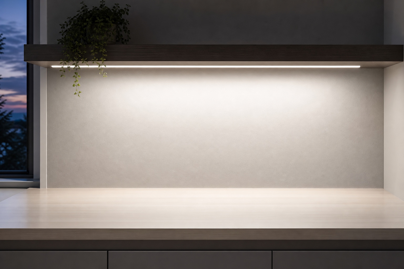
Designing Commercial Lighting with 24V Constant Voltage Systems: A Practical Guide

Among the various voltage options for constant voltage LED systems — 12V, 24V, 36V, 48V — 24V has emerged as the sweet spot for most commercial applications. It balances the competing demands of voltage drop, cable sizing, safety, and product availability in a way that no other voltage does. Designing a 24V system well, however, requires more than just picking a driver and connecting LED strips. It demands attention to load calculation, voltage drop, inrush current, cable sizing, and the physical layout of the installation. This guide walks through the key design decisions, using a 100W, 24V driver as the reference point.
Why 24V rather than 12V? The answer lies in Ohm's law. For a given power level, the current is inversely proportional to the voltage. A 100W load at 12V draws 8.33A; at 24V it draws 4.16A. This halving of current has cascading benefits. Cable cross-section is determined by current-carrying capacity and voltage drop. A 4.16A load can be carried by a 0.5mm² cable over short distances, while an 8.33A load requires at least 0.75mm² and often 1.0mm². Over a 10-meter run, the voltage drop for a 0.75mm² cable at 8.33A is approximately 3.6V — 30 percent of a 12V supply, which is completely unacceptable. The same cable at 4.16A drops 1.8V, which is 7.5 percent of a 24V supply — still high, but manageable with a larger cable or a shorter run. In practical terms, 24V systems can run cables two to three times farther than 12V systems for the same voltage drop percentage, which is often the difference between a feasible installation and one that requires the driver to be mounted inches from the LED load.
Why 24V rather than 48V? 48V further reduces current — a 100W load draws only 2.08A — and voltage drop is even less of a concern. But 48V sits closer to the SELV boundary of 120V DC, and while it is still SELV-compliant, the margin is smaller. More importantly, the ecosystem of 48V LED products is much narrower than that of 24V. The vast majority of LED strips, flexible tapes, signage modules, controllers, dimmers, and accessories are designed for 12V or 24V. 24V products are available in every color temperature, CRI, beam angle, and IP rating that 12V products offer, while 48V products are largely limited to specialized applications such as long-length LED strips or high-voltage cove lighting. For a commercial project that may use a mix of fixture types — strips, downlights, signage, accent lighting — 24V offers the broadest product selection and the most competitive pricing.
Load calculation is the first step in any 24V system design. The total connected load must not exceed the driver's rated output power, and a safety margin of 10 to 20 percent is recommended to account for LED tolerance, temperature effects, and future additions. A 100W driver should therefore be loaded to no more than 80 to 90W in practice. If the design calls for 96W of LED strips, either reduce the load or step up to a 150W driver. Overloading a constant voltage driver does not cause an immediate catastrophic failure — most drivers include overcurrent protection that limits the output current — but it causes the output voltage to sag, which dims the LEDs and can cause visible brightness variation across the installation. Chronic overloading also stresses the driver's components and shortens its lifetime.
Voltage drop calculation is the second step, and it is where many designs go wrong. The voltage drop in a cable is given by V_drop = 2 × I × L × R, where I is the current in amps, L is the one-way length in meters, and R is the resistance per meter of the cable in ohms. The factor of 2 accounts for the round trip (positive and negative conductors). For a 24V system, a maximum voltage drop of 5 percent (1.2V) at the farthest load is a reasonable design target, though some LED strips tolerate up to 10 percent. Using the formula, a 100W load (4.16A) on a 10-meter run of 0.75mm² cable (R = 0.023 ohms/m) gives V_drop = 2 × 4.16 × 10 × 0.023 = 1.91V, or 8 percent — above the 5 percent target. Stepping up to 1.0mm² cable (R = 0.017 ohms/m) gives V_drop = 1.41V, or 5.9 percent — close to the target. 1.5mm² cable (R = 0.0115 ohms/m) gives 0.96V, or 4 percent — comfortably within the target. The design decision is whether to use a larger cable, shorten the run, or move the driver closer to the load. In many commercial installations, the driver is mounted in a ceiling cavity near the LED strips, keeping the 24V runs short and minimizing voltage drop.
An often-overlooked factor is that LED strips themselves have resistance. A standard 5050 LED strip on a 1-oz PCB has a voltage drop along its length that becomes significant beyond 5 meters. This is why most LED strips are rated for maximum run lengths of 5 or 10 meters, and why longer runs require power injection at both ends or at intermediate points. The driver's output voltage is 24V at the driver terminals, but by the time it reaches the end of a 10-meter strip, it may have dropped to 22V or lower, causing visible dimming at the far end. Power injection — running additional 24V wires from the driver to the midpoint or end of the strip — solves this problem by providing a lower-resistance path for the current. The design must account for both cable voltage drop and strip voltage drop, not just one or the other.
Inrush current is another design consideration. When a constant voltage driver is first powered on, the input capacitors in the PFC stage and the bulk capacitor on the DC bus charge rapidly, drawing a large transient current from the mains. This inrush current can be 20 to 50 times the steady-state input current, lasting for a few milliseconds. For a single 100W driver with a steady-state input current of 0.56A, the inrush might peak at 15 to 25A. This is not a problem for a single driver on a 16A circuit breaker, but when 20 drivers are switched on simultaneously — for example, by a contactor or a time clock — the combined inrush can reach 300 to 500A, which will trip a standard B-curve circuit breaker. The solution is to either use a C-curve or D-curve breaker that can tolerate higher inrush, stagger the startup of the drivers using sequential switching, or use drivers with active inrush current limiting. The PV100's input current rating of 0.56A max already accounts for the steady-state current, but the inrush must be considered at the circuit design level.
Circuit breaker and fuse sizing should be based on the steady-state input current, not the inrush. A 100W driver at 230V draws 0.56A. Ten drivers on the same circuit draw 5.6A steady-state, so a 10A or 16A B-curve breaker is appropriate for steady-state protection. But if all ten drivers are switched simultaneously, the inrush may trip a B-curve breaker. In that case, a C-curve breaker (which allows 5 to 10 times rated current for transient periods) is a better choice, provided the downstream wiring can tolerate the higher fault current. The local electrical code will specify the maximum breaker rating for a given cable size, and the design must comply with those requirements.
Parallel connection is the standard wiring method for constant voltage systems. All LED loads are connected in parallel across the 24V bus, with each load drawing its own current based on its power rating. The total current is the sum of the individual load currents, and it must not exceed the driver's rated output current of 4.16A for a 100W driver. This parallel architecture makes it easy to add or remove loads without affecting the voltage across the remaining loads, as long as the total current stays within the rating. It also means that a short circuit in one branch will pull down the entire bus, so branch-level fusing or the driver's built-in short-circuit protection is essential. Most modern LED drivers include short-circuit protection that hiccups — repeatedly shutting down and restarting — until the short is removed, protecting both the driver and the wiring.
Physical layout considerations include driver mounting location, accessibility for maintenance, and thermal environment. Drivers should be mounted in a location that is accessible for replacement — a ceiling tile, a junction box with a removable cover, or a dedicated equipment closet. They should not be buried in insulation or enclosed in airtight spaces without ventilation, as this raises the ambient temperature and reduces lifetime. The driver's input side (mains voltage) must be enclosed according to local electrical code, while the output side (24V SELV) can be more exposed. The separation between mains and SELV wiring must be maintained — they should not run in the same conduit or junction box without appropriate barriers.
A well-designed 24V constant voltage system is reliable, efficient, and cost-effective. It starts with the right driver — one with adequate power rating, high efficiency, active PFC, and proper safety certifications — and proceeds through careful load calculation, voltage drop analysis, cable sizing, and circuit protection. The 24V voltage level provides the best balance of practicality and performance for most commercial applications, and the breadth of available products makes it easy to find the right LED fixtures for any design. By following the principles outlined above, a lighting designer can create a 24V system that delivers consistent brightness, minimal energy waste, and years of trouble-free operation.
Harmonic Distortion and Power Quality: The Hidden Impact of LED Drivers on Building Infrastructure
Non-Dimmable LED Drivers: When Simplicity Delivers Better Reliability
Related Article